We took our layout “Die Keinnamebahn” to the Chesterfield Model Railway Society annual show at Bakewell, Derbyshire for their weekend-long exhibition.
We set up on the Friday evening and immediately had DCC control problems. Locos would start in the fiddle yard but would be jerky in operation and would ‘die’ about 1/4 of the way down the layout. A thorough track clean was undertaken and the voltage measured at several points on the track including the ‘sticky’ points. 14v was measured at all points.
We tried several locos and they all displayed this erratic and uncontrollable behaviour.
We disconnected all the boards barring the central power feed board and tested locos on that board, they still ‘misbehaved’!
Suspecting a fault in the SPROG 3 controller, it was replaced with a brand new unit. This had no effect on the problem.
The Raspberry Pi computer was then swapped for the emergency backup unit using a different version of the JMRI software. No change!
The DCC control was then passed to a Digitrax DSC51 manually controlled unit. No change!
A fellow operator loaned us a Gaugemaster Prodigy DCC system to try, and you guessed it, No change!
We were pretty much stumped at this point with the layout unable to run locos but, all the hardwired DCC systems, Digitrax DS64 and DS52 point controllers, the ESU SwitchPilot Servo units and the hardwired DCC decoder for the turntable working perfectly!
At this point we checked the number of WiFi systems in the building using an app on my Android phone and found 9 strong WiFi signals. We also discovered that the building had a mobile phone mast on its roof.
It was at this point that I remembered the days when your stereo would go “tick, tick, tick, buzzzz” when a mobile phone was nearby. Could this be the problem in that the rails were picking up these signals (used to initialise and negotiate the connection between the mast and the phone) and that the DCC decoders were being overwhelmed by induced noise spikes? Bakewell is a tourist town in the summer and thousands of mobile phones will be constantly connecting to the mast on the building.
The “tick, tick, tick, buzzz” sound is a subharmonic of the rapid switching on and off of the gigahertz frequency phone signals during the connection negotiation. A typical DCC control signal is shown below. With the spacing between pulses and the puzzle width being 100ms for a 0 (zero) and 58ms for a 1 (one).

If you get any electrical spikes induced into your layout that approach the track voltage (14V in our case) then the DCC packet can be corrupted or masked.
We were unable to get the system running on the Saturday and had to pack up and go home.
Once home the locos were tested and some decoders were found to have had their settings altered! One loco would not run at all but when the decoder was removed and tested on my ESU decoder tester it was discovered that the speed settings had all been set to 0 (zero), in all other respects the loco was fine once the decoder was reprogrammed and replaced. Other locos had the number of speed steps changed to 14 instead of the original 128 steps.
This indicated that we had had major induced voltages in our tracks and that we were lucky in not having had the £600 worth of DCC decoders physically damaged.
Because the problem was even displayed on a single 400mm baseboard it indicated that the problem was an induced high frequency. Mobile phone networks in the U.K. use frequencies from 800 MHz to 2600 MHz. A piece of track 375mm long is almost perfectly tuned to act as an aerial for the 800MHz end of the phone spectrum whilst one of 115mm is tuned for the 2600MHz frequencies. 5G Services will use the 3.4 – 3.8 GHz bands meaning ‘aerials’ of approximately 80mm will be affected.
The following table list the frequencies used by the U.K. phone companies
Popular UK Mobile carriers & their frequencies
- Three (3) 4G – 800/1800MHz. 3G – 2100.
- T-Mobile, Orange, EE. 4G – 800/1800/2600MHz. 3G – 2100.
- O2 / Telefonica. 4G – 800MHz. 3G – 900/2100.
- Vodafone. 4G – 800/2600MHz. 3G – 900/2100.
- Giff Gaff. 4G – 800MHz. …
- Tesco. 4G – 800MHz. …
- BT. 4G – 800/1800/2600MHz. …
- Virgin Mobile. 4G – 800/1800/2600MHz.
The emergency services in the U.K. use the frequencies listed by OFCOM here
https://www.ofcom.org.uk/__data/assets/pdf_file/0021/103296/fat-emergency-services.pdf
It is clear to me that as more and more exhibition venues, especially schools and civic venues, have mobile phone or emergency services masts placed on or near them, and WiFi networks proliferate, then the radio ‘pollution’ problems for DCC controlled layouts will only increase.
Possible Solutions
After this unmitigated radio-induced signals disaster at Bakewell I am determined to try and prevent it happening again. In furtherance of this aim the following changes to “Die Keinnamebahn” have been started.
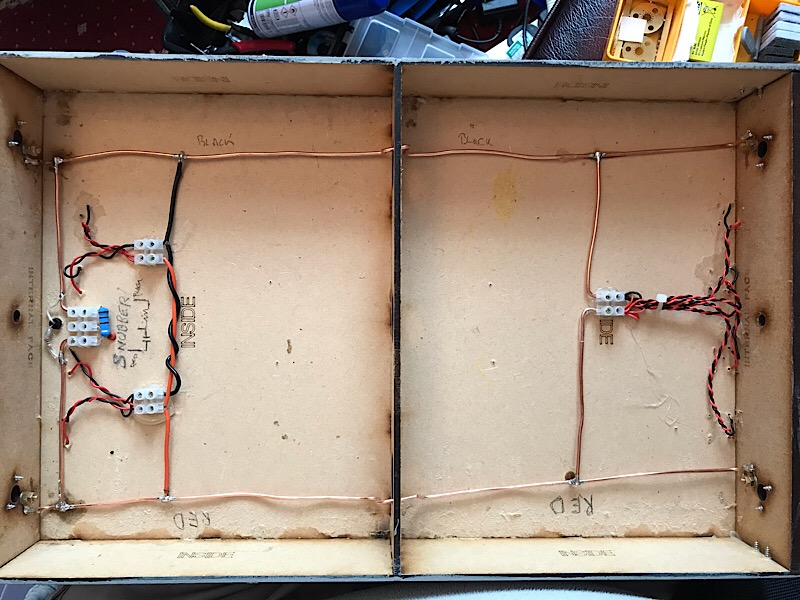
- All baseboards will have 2mm solid copper busbars fitted rather than relying on the old n-Gauge tracks I originally used.
- All baseboards will have the tracks fed from the busbars at both ends of the baseboard rather than relying on a centre feed. This will prevent reflections from open-ended rails which may have cause standing waves of interference to develop which could reach a disrupting voltage level.
- A ferrite core will be fitted to the incoming power lead to prevent that lead being an aerial feeding the radio signals into the layout.
- All, or as near as possible, wires that feed the track to be replaced with twisted pairs to reduced induced voltages.
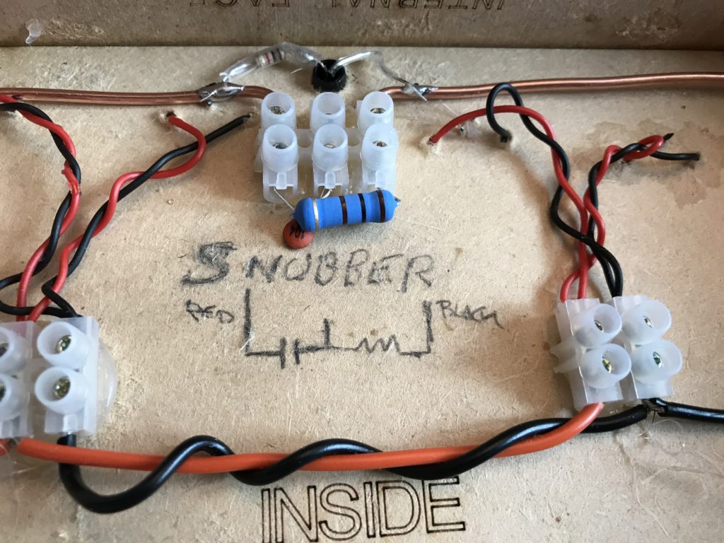
- “Die Keinnamebahn” is an end-to-end layout, and therefore a potential 3.6m long aerial. Low pass filters are be fitted to both ends of the layout to prevent reflections of any radio wave interference. These are simply a 50v 0.1μF ceramic capacitor in series with a 100Ω 2W resistor connected across the power busbars at the layout’s ends. These will not affect the DCC signals but will prevent signals of >15KHz from reflecting and enhancing in the rails. There will be a small power ‘drain’ of about 0.2 – 0.33 Watts per filter and a 2W resistor is recommended to deal with that power.


All this work will be undertaken before we next exhibit “Die Keinnamebahn” again at the North Wales N-Gauge Society show at Conwy, North Wales on 6 & 7th July. Only then will we know if the above work was effective.
