I wanted to use some DCC Concepts 2-aspect ground signals that I had bought. They came with two DCC Concepts Alpha Mimic LED controllers but at 50 UKP each, and capable of operating 24 LEDs each, they are too expensive to use on Die Keinnamebahn where only a few signals are on each board and only the two DCC signals connect each board together via brass pattern-makers’ dowels.

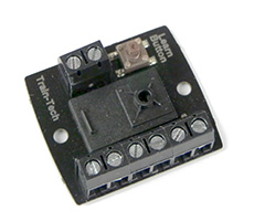
For controlling my Viessmann signals I use Train-Tech SC1 and SC2 DCC signal decoders. The wiring diagram for these require you to have a common anode or cathode for all the LEDs with the other wire going to the switched connector on the SC1 board. How would I be able to connect the DCC Concepts ground signals which only have 2 wires, the red and green LEDs being wired as an opposing pair in parallel, working by changing the polarity of the feed voltage.
Whilst looking online for “DCC SC1” I found another site (Harman as signalist.co.uk) selling a DCC signal controller, also called SC1, but of a different design. That design said that you could connect a pair of LEDs with opposing polarity across pins 1 & 2 instead of wiring them with common cathode or anode and to pins 1 & 2.
i decide to see if this would also be true of the Train-Tech SC1 unit. I first checked out what happens as the signal is set or cleared under DCC control by connecting a digital multimeter across pins 1 & 2. The voltage changed from +2.8vdc to -2.8vdc! This was very promising and so I then connected a pair of LED, with opposing polarities, to pins 1 & 2. The result was a pair of LEDs that alternatively illuminated as the DCC command to set and clear the accessory was done. No extra resistors were required as this is handled by the Train-Tech SC1.
This now means I can use the 17 UKP Train-Tech SC1 signals decoders instead of the 50 UKP DCC Concepts Alpha decoders to operate my 24 new red/green twin wire ground signals where only a few signal units are needed on a baseboard.
